Fedora Can't Read the Ctr While Initializing I8042
The PS/2 Controller (oft called a "Keyboard controller") is located on the mainboard. In the early days the controller was a single fleck (Intel 8042). As of today it is function of the Advanced Integrated Peripheral.
The name is misleading because the controller does more than than controlling communication with PS/ii devices.
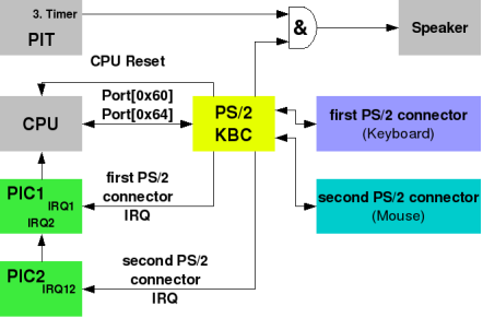
Overview of the PS/two-Controller
Contents
- 1 History
- one.1 Translation
- 2 USB Legacy Support
- three Buffer Naming Perspective
- 4 PS/ii Controller IO Ports
- 4.i Data Port
- 4.ii Condition Register
- 4.3 Command Register
- 5 PS/two Controller Commands
- 5.1 PS/two Controller Configuration Byte
- 5.2 PS/2 Controller Output Port
- six Initialising the PS/2 Controller
- 6.1 Step 1: Initialise USB Controllers
- half-dozen.2 Step ii: Determine if the PS/two Controller Exists
- 6.3 Step 3: Disable Devices
- half-dozen.four Step 4: Flush The Output Buffer
- 6.5 Step 5: Set the Controller Configuration Byte
- 6.6 Footstep six: Perform Controller Self Test
- 6.7 Stride vii: Decide If At that place Are 2 Channels
- vi.viii Footstep 8: Perform Interface Tests
- 6.9 Step 9: Enable Devices
- six.10 Step x: Reset Devices
- 7 Detecting PS/two Device Types
- 8 Hot Plug PS/two Devices
- ix Sending Bytes To Device/s
- 9.1 First PS/two Port
- 9.two Second PS/2 Port
- 10 Receiving Bytes From Device/due south
- x.i Polling
- 10.2 Interrupts
- xi CPU Reset
- 12 See Likewise
- 12.1 Threads
- 12.2 External Links
History
A multi-purpose PPI (Intel 8048, Programmable peripheral interface; also used to control other functions, like sound and parity error) controlled the original uni-directional, unmarried aqueduct IBM PC and PC-XT keyboard interface. The XT controller is 100% obsolete and won't exist discussed further in this page.
With the PC-AT, IBM introduced new keyboards (with a new bi-directional protocol) and a new keyboard controller (Intel 8042). The old PPI was non part of the motherboard any more than.
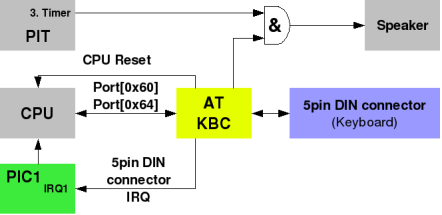
Overview of the AT-Controller
The 8042 was a powerful micro-controller. To reduce costs, some of the general purpose input/output capabilities of the AT controller was used to control various functions unrelated to the keyboard, including:
- System Reset
- The A20-Gate
With the introduction of the PS/2 series, the primary change to the keyboard controller subsystem was its expansion to control both a keyboard and a mouse. Previously PC and compatible mice were connected to dissimilar concrete interfaces, including Serial Ports. The AT keyboard controller and its "clones" were not capable of interfacing the new PS/2 mouse. Somewhen (around the late 80486 and early on Pentium time frame) PS/2 fashion mice became popular, and "PC compatible" controllers take supported dual channels from so on (nominally i keyboard and ane mouse).
For the keyboard functions proper, the PS2 and AT controllers are very similar. The adjunction of a second channel (for the mouse) has forced nevertheless to redefine a few condition and control $.25.
Translation
The original IBM-PC keyboards (using the former XT interface) used "scan code set 1". The new AT keyboards generated dissimilar browse codes, or "scan code set 2". This change would have created compatibility bug for software that was expecting unlike browse codes from the keyboard. To avert the compatibility problem, the keyboard controller supports a translation way. If translation is enabled the controller will interpret "scan lawmaking set 2" into "scan code set up 1".
Whenever this translation is enabled (and by default, information technology is) there is no manner to reverse it in software. For example, if you receive the byte 0xB5 from the controller, then you can't know if the original data (sent to the controller by the device) was the byte 0xB5; or if it was the two bytes 0xF0, 0x33; or if it was the two bytes 0xF0, 0xB3.
For software to really use "scan lawmaking set two" (or the even newer, rarely used, "scan code set 3"), or to permit different devices to exist used in the keyboard port, you demand to disable this translation to avoid having the information from the device mangled.
USB Legacy Support
By modern standards you will find many PCs bundled with USB input devices. Some PCs may non even take PS/two connectors at all. To remain compatible with old software, the mainboard emulates USB Keyboards and Mice as PS/ii devices. This is called USB Legacy Support.
Because the implementation differ past manufacturer and mainboard there are flaws and sometimes even bugs:
- Some emulation layers besides handle the communication with the existent PS/2 connectors regardless of any continued USB device. And so perchance not all capabilities of the PS/ii connectors and devices tin can be used. For example extended mouse modes needed to use the scroll wheel won't work or the keyboard only works on the first PS/2 connector and the mouse only on the 2d connector.
- The SMM BIOS that's providing the PS/2 USB Legacy Support may not support extended retention techniques or Long Mode and may cause organization crashes.
This USB Legacy Back up should be disabled past the Bone as soon as the OS initialises the USB Controller, and this should exist done before the OS attempts to initialise the real PS/two controller. Otherwise the Os would only initialise the emulated PS/2 controller and at that place's a big take a chance of issues caused past deficiencies in the firmware's emulation.
Buffer Naming Perspective
The PS/ii controller has two (i byte) buffers for information — one buffer for data received from devices that is waiting to be read past your OS, and one for data written by your Os that is waiting to be sent to a PS/2 device. Most information sheets for PS/2 controllers are written from the perspective of the PS/2 device and non from the perspective of software running on the host. Because of this, the names given to these buffers are the contrary of what you expect: the output buffer contains a device'south output information (data waiting to be read by software), and the input buffer contains a device'south input (data that was sent by software).
PS/ii Controller IO Ports
The PS/2 Controller itself uses ii IO ports (IO ports 0x60 and 0x64). Like many IO ports, reads and writes may access different internal registers.
Historical notation: The PC-XT PPI had used port 0x61 to reset the keyboard interrupt request bespeak (amidst other unrelated functions). Port 0x61 has no keyboard related functions on AT and PS/2 compatibles.
| IO Port | Admission Type | Purpose |
|---|---|---|
| 0x60 | Read/Write | Information Port |
| 0x64 | Read | Status Register |
| 0x64 | Write | Command Register |
Information Port
The Data Port (IO Port 0x60) is used for reading information that was received from a PS/ii device or from the PS/two controller itself and writing data to a PS/2 device or to the PS/ii controller itself.
Status Annals
The Status Annals contains various flags that show the country of the PS/2 controller. The meanings for each bit are:
| Chip | Meaning |
|---|---|
| 0 | Output buffer condition (0 = empty, one = total) (must be set before attempting to read data from IO port 0x60) |
| 1 | Input buffer status (0 = empty, 1 = full) (must exist clear before attempting to write information to IO port 0x60 or IO port 0x64) |
| 2 | System Flag Meant to be cleared on reset and set by firmware (via. PS/two Controller Configuration Byte) if the organisation passes self tests (POST) |
| iii | Command/data (0 = data written to input buffer is data for PS/two device, one = information written to input buffer is information for PS/2 controller command) |
| four | Unknown (chipset specific) May be "keyboard lock" (more likely unused on modern systems) |
| 5 | Unknown (chipset specific) May be "receive time-out" or "second PS/two port output buffer full" |
| 6 | Time-out error (0 = no error, one = fourth dimension-out mistake) |
| 7 | Parity fault (0 = no fault, i = parity error) |
Command Register
The Control Port (IO Port 0x64) is used for sending commands to the PS/ii Controller (non to PS/2 devices).
PS/2 Controller Commands
The PS/2 Controller accepts commands and performs them. These commands should not be confused with bytes sent to a PS/2 device (e.g. keyboard, mouse).
To send a command to the controller, write the control byte to IO port 0x64. If in that location is a "next byte" (the command is 2 bytes) then the next byte needs to exist written to IO Port 0x60 after making sure that the controller is ready for it (past making sure scrap 1 of the Condition Register is clear). If at that place is a response byte, then the response byte needs to be read from IO Port 0x60 after making sure information technology has arrived (by making sure flake 0 of the Condition Annals is prepare).
| Command Byte | Meaning | Response Byte |
|---|---|---|
| 0x20 | Read "byte 0" from internal RAM | Controller Configuration Byte (run into below) |
| 0x21 to 0x3F | Read "byte N" from internal RAM (where 'Northward' is the command byte & 0x1F) | Unknown (only the first byte of internal RAM has a standard purpose) |
| 0x60 | Write next byte to "byte 0" of internal RAM (Controller Configuration Byte, see beneath) | None |
| 0x61 to 0x7F | Write next byte to "byte N" of internal RAM (where 'N' is the control byte & 0x1F) | None |
| 0xA7 | Disable second PS/2 port (only if two PS/2 ports supported) | None |
| 0xA8 | Enable second PS/2 port (only if two PS/2 ports supported) | None |
| 0xA9 | Test second PS/two port (only if ii PS/ii ports supported) | 0x00 exam passed 0x01 clock line stuck low 0x02 clock line stuck loftier 0x03 information line stuck low 0x04 data line stuck high |
| 0xAA | Test PS/two Controller | 0x55 test passed 0xFC test failed |
| 0xAB | Test first PS/ii port | 0x00 exam passed 0x01 clock line stuck depression 0x02 clock line stuck high 0x03 data line stuck low 0x04 data line stuck loftier |
| 0xAC | Diagnostic dump (read all bytes of internal RAM) | Unknown |
| 0xAD | Disable first PS/2 port | None |
| 0xAE | Enable showtime PS/2 port | None |
| 0xC0 | Read controller input port | Unknown (none of these bits have a standard/defined purpose) |
| 0xC1 | Copy bits 0 to 3 of input port to condition bits 4 to vii | None |
| 0xC2 | Copy bits 4 to seven of input port to status $.25 4 to 7 | None |
| 0xD0 | Read Controller Output Port | Controller Output Port (see below) |
| 0xD1 | Write next byte to Controller Output Port (encounter below) Note: Check if output buffer is empty first | None |
| 0xD2 | Write next byte to first PS/2 port output buffer (only if 2 PS/two ports supported) (makes information technology look like the byte written was received from the first PS/2 port) | None |
| 0xD3 | Write next byte to 2nd PS/2 port output buffer (simply if 2 PS/two ports supported) (makes it look like the byte written was received from the second PS/ii port) | None |
| 0xD4 | Write next byte to second PS/two port input buffer (only if 2 PS/2 ports supported) (sends side by side byte to the 2d PS/2 port) | None |
| 0xF0 to 0xFF | Pulse output line depression for 6 ms. $.25 0 to 3 are used every bit a mask (0 = pulse line, i = don't pulse line) and correspond to four different output lines. Note: Chip 0 corresponds to the "reset" line. The other output lines don't take a standard/defined purpose. | None |
Annotation: Command bytes not listed in the table above should be treated equally either "chipset specific" or "unknown" and shouldn't be issued. Commands bytes that are marked as "only if 2 PS/2 ports supported" should besides exist treated every bit either "chipset specific" or "unknown" if the controller but supports one PS/2 port.
PS/two Controller Configuration Byte
Commands 0x20 and 0x60 let you read and write the PS/2 Controller Configuration Byte. This configuration byte has the following format:
| Bit | Significant |
|---|---|
| 0 | Offset PS/2 port interrupt (1 = enabled, 0 = disabled) |
| i | 2d PS/2 port interrupt (i = enabled, 0 = disabled, only if 2 PS/2 ports supported) |
| 2 | System Flag (ane = system passed Mail, 0 = your OS shouldn't be running) |
| iii | Should be zero |
| 4 | Beginning PS/ii port clock (one = disabled, 0 = enabled) |
| 5 | Second PS/2 port clock (1 = disabled, 0 = enabled, just if 2 PS/2 ports supported) |
| half dozen | Outset PS/2 port translation (i = enabled, 0 = disabled) |
| vii | Must be zero |
Notation: Bits listed in the tabular array higher up every bit "unknown" should be treated as either "chipset specific" or "unknown". $.25 that are marked as "only if two PS/2 ports supported" should also be treated as either "chipset specific" or "unknown" if the controller only supports ane PS/2 port.
PS/ii Controller Output Port
Commands 0xD0 and 0xD1 let you read and write the PS/2 Controller Output Port. This output port has the post-obit format:
| Bit | Meaning |
|---|---|
| 0 | Organization reset (output) Alert e'er set to '1'. You lot need to pulse the reset line (e.g. using control 0xFE), and setting this flake to '0' tin can lock the computer up ("reset forever"). |
| 1 | A20 gate (output) |
| two | Second PS/ii port clock (output, only if 2 PS/two ports supported) |
| 3 | Second PS/two port information (output, only if 2 PS/2 ports supported) |
| 4 | Output buffer full with byte from showtime PS/2 port (continued to IRQ1) |
| 5 | Output buffer full with byte from second PS/2 port (connected to IRQ12, only if two PS/2 ports supported) |
| 6 | First PS/two port clock (output) |
| 7 | Get-go PS/ii port data (output) |
Note: Bits that are marked in the table above as "merely if two PS/2 ports supported" should be treated every bit either "chipset specific" or "unknown" if the controller but supports ane PS/2 port.
Initialising the PS/2 Controller
Some people assume the PS/ii controller exists and was configured correctly by firmware. This approach can work, but isn't very robust and doesn't correctly support "less simple" scenarios. Examples of why this approach may not piece of work well include:
- Something (e.g. a Boot Manager) left the PS/2 Controller in a dodgy state
- The PS/2 Controller has hardware faults and your OS did no testing
- At that place'due south a USB keyboard and a PS/ii mouse, and the BIOS didn't bother initialising the PS/2 controller considering it was using USB Legacy Support and not using the mouse
- You want to reliably send data to the 2d PS/2 device on older hardware and accept to know the second PS/2 port exists (see the warning for "Sending Bytes To The Second PS/ii Port" below).
The following steps are for "comprehensive PS/ii Controller initialisation". It may be excessive for your purposes, and a more express version of it may be more than suitable. However, it'southward easy enough to (selectively) remove steps from the following description.
Step 1: Initialise USB Controllers
This has nothing to do with the PS/ii Controller or PS/2 Devices, however if the arrangement is using (typically limited/dodgy) USB Legacy Back up it will interfere with PS/2 Controller initialisation. Therefore you need to initialise USB controllers and disable USB Legacy Support beforehand.
Footstep 2: Determine if the PS/ii Controller Exists
Before you touch the PS/2 controller at all, you should determine if it exists. On some systems (e.g. 80x86 Apple machines) it doesn't exist and any attempt to touch information technology can crusade a system crash. The correct way to exercise this is is with ACPI. Bank check chip i (value = 2, the "8042" flag) in the "IA PC Boot Architecture Flags" field at commencement 109 in the Stock-still ACPI Clarification Table (FADT). If this bit is clear, then at that place is no PS/2 Controller to configure. Otherwise, if the bit is prepare, or the organization doesn't support ACPI (no ACPI tables and no FADT) then in that location is a PS/2 Controller.
Step 3: Disable Devices
So that any PS/2 devices can't send data at the wrong time and mess up your initialisation; start by sending a control 0xAD and control 0xA7 to the PS/2 controller. If the controller is a "single channel" device, information technology will ignore the "control 0xA7".
Step four: Flush The Output Buffer
Sometimes (e.chiliad. due to interrupt controlled initialisation causing a lost IRQ) data can get stuck in the PS/two controller's output buffer. To baby-sit against this, now that the devices are disabled (and can't send more data to the output buffer) it tin be a good idea to flush the controller's output buffer. There's 2 ways to do this - poll bit 0 of the Condition Annals (while reading from IO Port 0x60 if/when flake 0 becomes set up), or read from IO Port 0x60 without testing bit 0. Either manner should work (as you're discarding the information and don't care what it was).
Footstep 5: Set the Controller Configuration Byte
Considering some bits of the Controller Configuration Byte are "unknown", this ways reading the erstwhile value (command 0x20), changing some $.25, and so writing the changed value back (command 0x60). You want to disable all IRQs and disable translation (clear $.25 0, 1 and 6).
While y'all've got the Configuration Byte, exam if bit 5 was set up. If information technology was clear, then you know information technology can't exist a "dual channel" PS/2 controller (because the second PS/2 port should be disabled).
Step six: Perform Controller Cocky Test
To test the PS/2 controller, send control 0xAA to it. Then wait for its response and check it replied with 0x55. Annotation: this can reset the PS/ii controller on some hardware (tested on a 2016 laptop). At the very least, the Controller Configuration Byte should be restored for compatibility with such hardware. You can either determine the correct value yourself based on the above table or restore the value read before issuing 0xAA.
Footstep 7: Make up one's mind If There Are 2 Channels
If y'all know it's a single channel controller (from Step v) then skip this step. Otherwise, send a command 0xAE to enable the second PS/2 port and read the Controller Configuration Byte again. Now scrap five of the Controller Configuration Byte should exist clear - if it's set then you know it can't be a "dual channel" PS/2 controller (because the second PS/2 port should be enabled). If it is a dual channel device, transport a command 0xA7 to disable the 2nd PS/2 port again.
Step viii: Perform Interface Tests
This step tests the PS/two ports. Apply command 0xAB to test the commencement PS/two port, then check the consequence. Then (if it's a "dual channel" controller) use command 0xA9 to test the second PS/ii port, and so check the result.
At this stage, check to run across how many PS/ii ports are left. If there aren't whatsoever that work you can just give up (display errors and terminate the PS/two Controller driver). Note: If one of the PS/2 ports on a dual PS/2 controller fails, then you tin can nonetheless proceed using/supporting the other PS/2 port.
Step 9: Enable Devices
Enable any PS/two port that exists and works using control 0xAE (for the kickoff port) and command 0xA8 (for the 2d port). If yous're using IRQs (recommended), besides enable interrupts for any (usable) PS/2 ports in the Controller Configuration Byte (set bit 0 for the first PS/2 port, and/or chip i for the second PS/2 port, so set it with command 0x60).
Footstep x: Reset Devices
All PS/ii devices should support the "reset" command (which is a control for the device, and non a control for the PS/2 Controller). To send the reset, just send the byte 0xFF to each (usable) device. The device/s will respond with 0xFA (success) or 0xFC (failure), or won't respond at all (no device present). If your code supports "hot-plug PS/two devices" (see later), then you tin can assume each device is "non present" and let the hot-plug code figure out that the device is present if/when 0xFA or 0xFC is received on a PS/ii port.
TODO: Potential wiki error, the 0xFF reset device command seems to respond 0xAA and and so 0xFA on cocky-test success, and PS/2_Keyboard agrees. --Sortie 14:15, 27 April 2015 (CDT)
TODO: Sortie: I don't recollect so, I transport byte 0xFF to keyboard (or mouse), and so received 0xFA (command acknowledged) after that received 0xAA (self examination successful) the last ane was 0x00 - mouse device ID. --Akasei 00:35, 19 February 2017 (UTC+one)
Detecting PS/2 Device Types
All PS/2 devices should back up the "identify" command and the "disable scanning" command (which are commands for the device, and non commands for the PS/ii Controller). The device should reply to the "place" command by sending a sequence of none, i or 2 identification bytes. Withal, if you just send the "place" command you tin't prevent the response from the "place" control from beingness mixed up with keyboard/mouse data. To fix this trouble, you need to transport the "disable scanning" command first. Disabling scanning means that the device ignores the user (e.k. keyboards ignore fundamental presses, mice ignore mouse movement and button presses, etc) and won't ship data to mess your device identification code up.
The full sequence is:
- Send the "disable scanning" command 0xF5 to the device
- Wait for the device to transport "ACK" back (0xFA)
- Transport the "identify" command 0xF2 to the device
- Expect for the device to send "ACK" back (0xFA)
- Expect for the device to send up to 2 bytes of reply, with a time-out to determine when information technology's finished (e.g. in instance it only sends 1 byte)
A partial list of responses includes:
| Byte/south | Device Blazon |
|---|---|
| None | Ancient AT keyboard with translation enabled in the PS/Controller (not possible for the 2d PS/two port) |
| 0x00 | Standard PS/2 mouse |
| 0x03 | Mouse with whorl wheel |
| 0x04 | 5-button mouse |
| 0xAB, 0x41 or 0xAB, 0xC1 | MF2 keyboard with translation enabled in the PS/Controller (not possible for the second PS/ii port) |
| 0xAB, 0x83 | MF2 keyboard |
Note: If anyone sees whatever other responses please add to the list higher up!
Once your PS/2 Controller driver knows what types of PS/two devices are present, it tin start suitable device drivers for those devices. Don't forget that we've left devices in a "scanning disabled" state.
Hot Plug PS/ii Devices
WARNING: PS/2 was never intentionally designed to support hot-plug. Commonly it is fine as nearly PS/2 controllers have reasonably robust IO lines, however some PS/2 controllers (mostly those in quondam chipsets) might get damaged.
Despite the alarm, near OSs (Windows, Linux, etc) practice back up hot-plug PS/ii. It is too relied on by old "mechanical switch" KVMs (which let multiple computers to share the aforementioned PS/2 devices by finer disconnecting the device from one estimator and connecting it to the adjacent).
When a PS/2 device is removed the PS/2 controller won't know. To work effectually this, when no information has been received from the device for some length of time (e.g. two seconds), an Bone can periodically test for the presence of the device by sending an "echo" command to the device and checking for a answer. If the device doesn't reply, then assume the device has been unplugged.
When a PS/2 device is kickoff powered up (e.g. when it is plugged in to a PS/2 port), the device should perform its Basic Assurance Examination and then endeavour to send a "BAT completion code". This means that software (e.thou. an OS) can automatically detect when a PS/2 device has been inserted. Note: If a device is removed and then another device (or the same device) is plugged in quickly enough, the software may not have had fourth dimension to find the removal.
When software detects that a device was plugged in it can determine the type of device (run into above). If the device was the same type every bit earlier software tin re-configure it so that the device is in the aforementioned state every bit it was before removal. This means that (for example) someone using an old "mechanical switch" KVMs doesn't lose state (things like keyboard LEDs, typematic rate, etc) when switching betwixt computers. If the device is not the same as earlier or there was no previously connected device, and then software may demand to start a new device commuter (and terminate the old device driver, if any).
Sending Bytes To Device/s
Unfortunately, the PS/two Controller does not support interrupt driven transmission (due east.thou. yous can't have a queue of bytes waiting to exist sent and then send each byte from within a "transmitter empty" IRQ handler). Fortunately, little data needs to be sent to typical PS/two devices and polling suffices.
First PS/2 Port
To send information to the first PS/2 Port:
- Set some timer or counter to employ equally a time-out
- Poll bit 1 of the Status Register ("Input buffer empty/total") until information technology becomes articulate, or until your time-out expires
- If the time-out expired, return an error
- Otherwise, write the information to the Data Port (IO port 0x60)
Second PS/2 Port
Sending data to the 2d PS/2 port is a piddling more complicated, as y'all need to send a command to the PS/2 controller to tell it that you want to talk to the second PS/two port instead of the first PS/2 port. To send data to the second PS/2 Port:
- Write the control 0xD4 to IO Port 0x64
- Ready some timer or counter to use as a time-out
- Poll bit 1 of the Status Register ("Input buffer empty/total") until information technology becomes clear, or until your time-out expires
- If the time-out expired, return an error
- Otherwise, write the information to the Information Port (IO port 0x60)
WARNING: If the PS/2 controller is an (older) "single PS/2 device simply" controller, if you effort to send a byte to the second PS/2 port the controller will ignore the control 0xD4 you send to IO Port 0x64, and therefore the byte you send will exist sent to the showtime PS/ii device. This means that (if you support older hardware) to reliably transport information to the second device you accept to know that the PS/2 Controller really has a second PS/2 port.
Receiving Bytes From Device/s
There are 2 ways to receive bytes from device/s: polling and using IRQ.
Polling
To poll, wait until scrap 0 of the Status Annals becomes set, so read the received byte of data from IO Port 0x60.
There are two major bug with polling. The first problem is that (like all polling) information technology wastes a lot of CPU time for zero. The second trouble is that if the PS/2 controller supports two PS/ii devices, there's no way to reliably decide which device sent the byte yous received, unless one of them is disabled and unable to send information.
Note: if the PS/two controller uses fleck v of the Status Annals equally a "second PS/two port output buffer full" flag, you'd however have issues trying to decide which device sent a byte of data you've received without race conditions. For example, at that place may be data from the 2d PS/2 device waiting for you when you check the flag, just earlier you read from IO Port 0x60 data from the showtime PS/two device might arrive and you might read information from the kickoff PS/2 device when yous think yous're reading data from the second PS/2 device. There'southward as well no easy way to know if the PS/two controller uses bit 5 of the Status Register equally a "2d PS/two port output buffer full" flag.
Interrupts
Using interrupts is easy. When IRQ1 occurs you just read from IO Port 0x60 (there is no demand to bank check bit 0 in the Condition Register first), send the EOI to the interrupt controller and return from the interrupt handler. You know that the information came from the starting time PS/2 device because y'all received an IRQ1.
When IRQ12 occurs you read from IO Port 0x60 (there is no need to check bit 0 in the Status Register starting time), ship the EOI to the interrupt controller/southward and return from the interrupt handler. You know that the data came from the second PS/2 device considering you received an IRQ12.
Unfortunately, there is i problem to worry about. If you send a command to the PS/ii controller that involves a response, the PS/ii controller may generate IRQ1, IRQ12, or no IRQ (depending on the firmware) when it puts the "response byte" into the buffer. In all three cases, you can't tell if the byte came from a PS/two device or the PS/2 controller. In the no IRQ case, yous additionally volition demand to poll for the byte. Fortunately, y'all should never demand to send a command to the PS/2 controller itself after initialisation (and you can disable IRQs and both PS/2 devices where necessary during initialisation).
CPU Reset
To trigger a CPU Reset, regardless of what state the CPU is in, write the value 0xFE to the Output port.
;Wait for a empty Input Buffer wait1: in al , 0x64 test al , 00000010b jne wait1 ;Ship 0xFE to the keyboard controller. mov al , 0xFE out 0x64 , al
Meet Also
- PS/2
- PL050 PS/2 Controller (ARM)
- PS/2 Keyboard
- PS/2 Mouse
Threads
- PS/2 controller initialisation
External Links
- SMS "8042" Datasheet
beardenhorpostiated1997.blogspot.com
Source: https://wiki.osdev.org/%228042%22_PS/2_Controller
0 Response to "Fedora Can't Read the Ctr While Initializing I8042"
Post a Comment